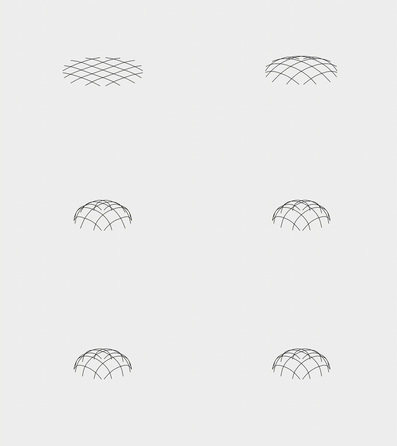
Form-finding of gridshell
Elastic gridshell refers to a network of elastic rods linked by joints and finds broad applications in the civil engineering community, such as the Helsinki Zoo’s observatory tower and Centre Pompidou Metz. In this case study, we examine the form-finding behavior of a hemispherical gridshell structure subjected to compressive loading. The grid is modeled with an initially flat shape, allowing it to deform and self-organize into a stable, curved configuration through controlled buckling. As the compressive forces act on the structure, the grid transitions into its equilibrium shape, illustrating the role of buckling in shape formation. This case highlights the ability of the DDG model to accurately capture the self-organizing behavior of slender elastic structures.
Simulation Initialization
To initialize the simulation, the following inputs are used:
- Geometry and connection:
- (i) Nodal positions: the position of the nodes, \(\mathbf{q}(t=0)\), with a total of \(N = 365\). The gridshell is constructed by the intersection of 10 orthogonally interconnected rods, creating an overall circular structure. The length of the two longest rods is set at \(L = 2.0\mathrm{~m}\).
- (ii) Stretching elements: the connections between the nodes, with a total of \(N_s = 376\).
- (iii) Bending elements: the connections between the edges, with a total of \(N_b = 366\).
- (iv) Target position: the final position for the 20 footprints.
- Physical parameters:
- (i) Young’s modulus, \(E = 100\mathrm{~MPa}\).
- (ii) Material density, \(\rho = 1000\mathrm{~kg/m^3}\).
- (iii) Cross-sectional radius, \(r_0 = 0.01\mathrm{~m}\), thus \(EI_1 = EI_2 = E \pi r_0^4 / 4\) and \(GJ = G \pi r_0^4 / 2\).
- (iv) Damping viscosity, \(\mu = 1.0\).
- (v) Gravity, \(\mathbf{g} = [0.0, 0.0, 10.0]^T\) \(\mathrm{m/s^2}\).
- (vi) The overall simulation is dynamic, i.e., \(\mathrm{ifStatic} = 0\).
- Numerical parameters:
- (i) Total simulation time, \(T = 10.0\mathrm{~s}\).
- (ii) Time step size, \(\mathrm{dt} = 0.01\mathrm{~s}\).
- (iii) Numerical tolerance, \(\mathrm{tol} = 1 \times 10^{-4}\).
- (iv) Maximum iterations, \(N_{\mathrm{iter}} = 10\).
- Boundary conditions:
- The 20 boundary nodes are fixed and manually moved along a prescribed path. Thus, the constrained array, \(\mathcal{FIX}\), can be constructed accordingly.
- Initial conditions:
- (i) Initial position is input from the nodal positions.
- (ii) Initial velocity is set to zeros for all nodes.
- Loading steps:
- (i) Perturbation step: a perturbation to the initial horizontal configuration is created by applying a gravitational force (with \(\mathbf{g} = [0.0, 0.0, 10.0]^T\mathrm{~m/s^2}\)) when \(t \le 1.0\mathrm{~s}\).
- (ii) Compression step: the footprints are moved to induce the form-finding process during \(1.0\mathrm{~s} < t < 5.0 \mathrm{~s}\).
- (iii) Remove Perturbation: gravity is removed to eliminate residual perturbations when \(t \ge 5.0\mathrm{~s}\).
Dynamic Rendering
