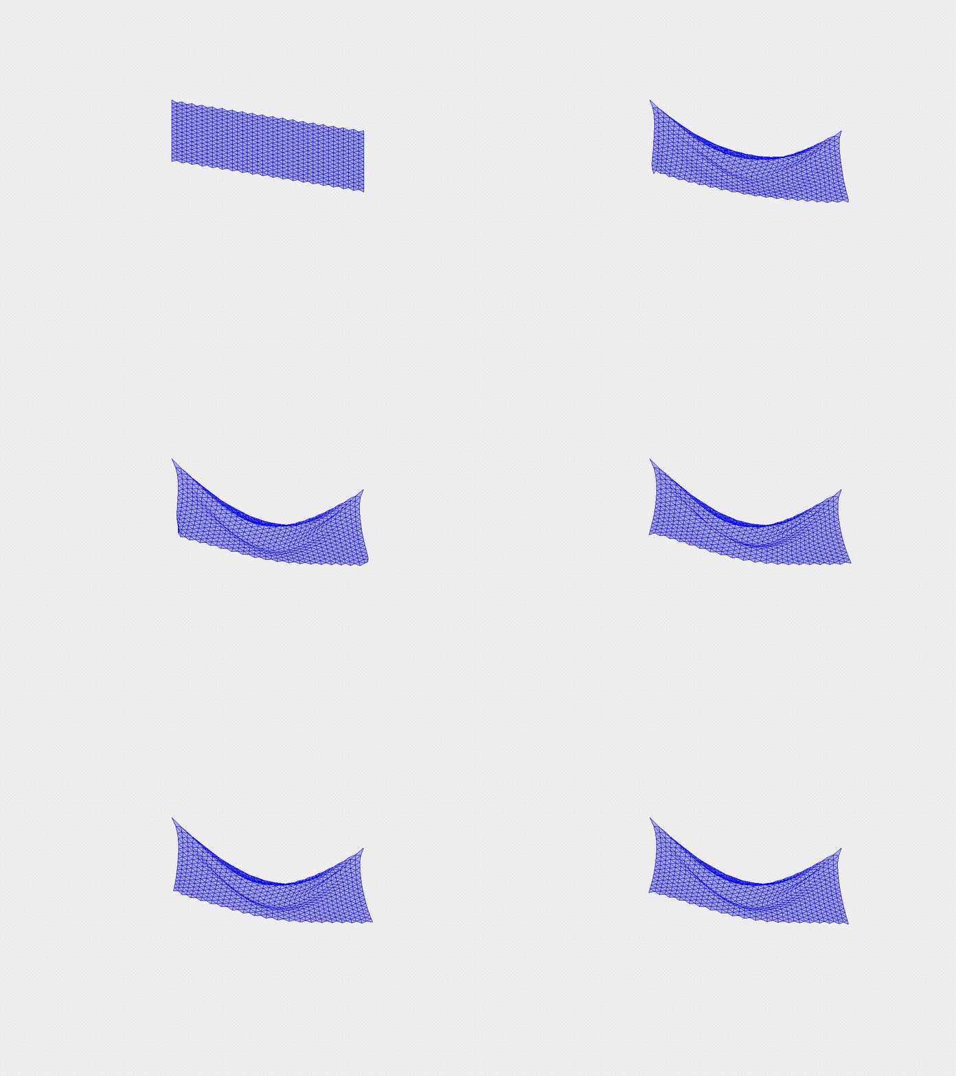
Plate wrinkling under gravity
Unlike the simple deflection case, this example introduces the phenomenon of wrinkling, a manifestation of instability in thin structures under compression. In this case study, we examine the wrinkling behavior of a plate subjected to gravity. The plate is modeled with two fixed boundary corners. As the plate deforms under the gravitational load, wrinkles develop due to instability in the structure. This case highlights the ability of the DDG model to accurately capture the complex deformation pattern of wrinkling.
Simulation Initialization
To initialize the simulation, the following inputs are used:
- Geometry and connection:
- (i) Nodal positions: the position of the nodes, \(\mathbf{q}(t=0)\), with a total of \(N=644\). The plate length is \(L=1.0\mathrm{~m}\) and width \(W=0.5\mathrm{~m}\).
- (ii) Stretching elements: connection of every two consecutive nodes, with a total of \(N_{s}=1821\).
- (iii) Triangular mesh, total number \(N_{t}=1178\).
- (iv) Bending elements: connection of every two triangular meshes, for a total of \(N_{b}=1713\).
- Physical parameters:
- (i) Young’s modulus, \(E=0.1\mathrm{~MPa}\).
- (ii) Material density, \(\rho=1000\mathrm{~kg/m^3}\).
- (iii) Plate thickness, \(h = 0.001\mathrm{~m}\).
- (iv) Gravitational field, \(\mathbf{g}=[1.0, 1.0, -30.0]^T \mathrm{~m/s^2}\).
- (v) Damping viscosity, \(\mu = 0.01\).
- (vi) The overall simulation is dynamic, i.e., \(\mathrm{ifStatic} = 0\).
- Numerical parameters:
- (i) Total simulation time, \(T=5.0\mathrm{~s}\).
- (ii) Time step size, \(\mathrm{dt} =0.01\mathrm{~s}\).
- (iii) Numerical tolerance, \(\mathrm{tol} = 1 \times 10^{-4}\).
- (iv) Maximum iterations, \(N_{\mathrm{iter}} = 10\).
- Boundary conditions:
- The two corner nodes, \(\{\mathbf x_{17}, \mathbf x_{644}\}\), are fixed; thus, the constrained array, \(\mathcal{FIX}\), can be constructed accordingly.
- Initial conditions:
- (i) Initial position is input from the nodal positions.
- (ii) Initial velocity is set to zeros for all nodes.
- Loading steps:
- External gravitational force is applied to each node throughout the simulation.
Dynamic Rendering
