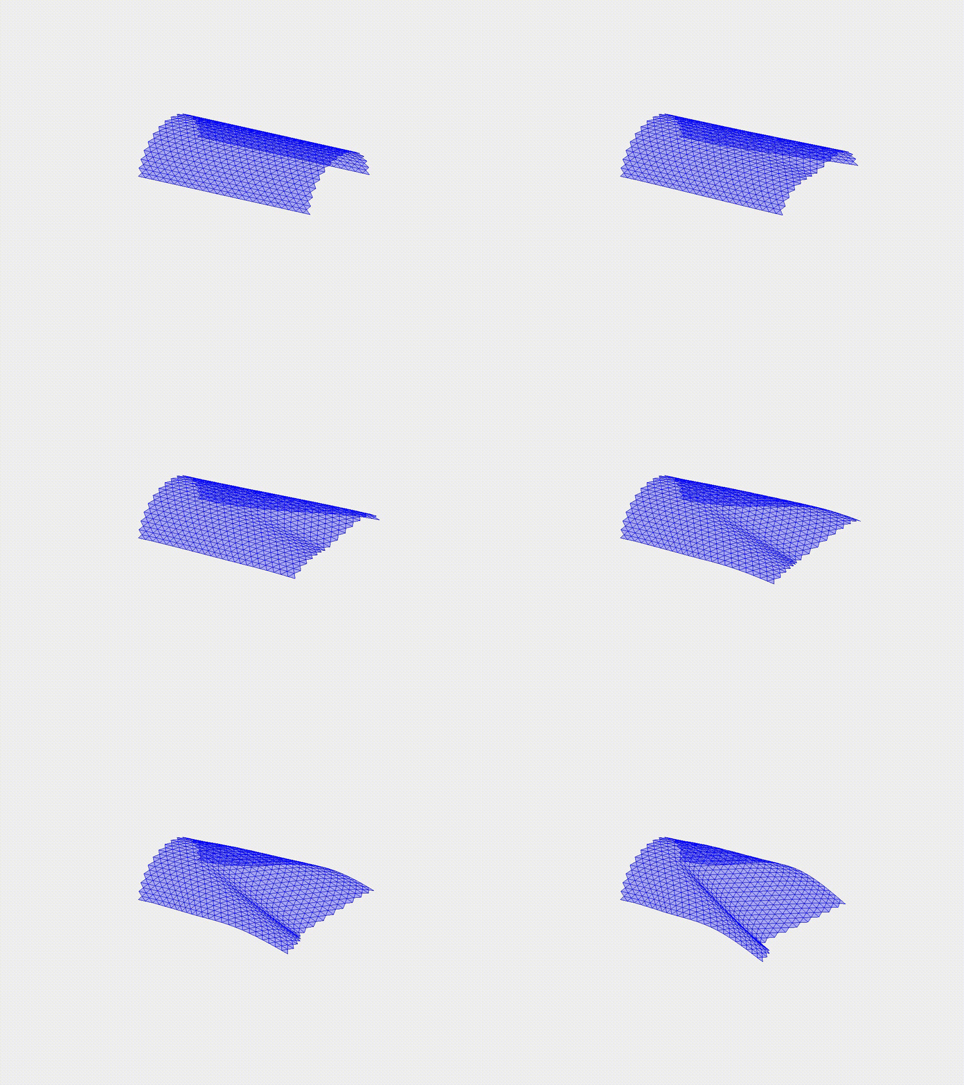
Indentation of the cylindrical shell
Shell indentation is a complicated problem and involves many non-linear buckling, snapping, and bifurcations. In this case study, we examine the indentation of a cylindrical shell under a point load. A half-cylindrical shell with a clamped-free boundary condition is considered, and a point indentation is applied at the middle point of the free end. This case highlights the ability of the DDG model to capture the complex deformed patterns of bifurcations in shell structures.
Simulation Initialization
To initialize the simulation, the following inputs are used:
- Geometry and connection:
- (i) Nodal positions: the position of the nodes, \(\mathbf{q}(t=0)\), with a total of \(N=760\). The half-cylindrical shell has a radius of \(R=1.0\mathrm{~m}\) and length \(L=3.0\mathrm{~m}\).
- (ii) Stretching elements: connection of every two consecutive nodes, with a total of \(N_{s}=2169\).
- (iii) Triangular mesh, total number \(N_{t}=1410\).
- (iv) Bending elements: connection of every two triangular meshes, with a total of \(N_{b}=2061\).
- Physical parameters:
- (i) Young’s modulus, \(E=1.0\mathrm{~MPa}\).
- (ii) Material density, \(\rho=1000\mathrm{~kg/m^3}\).
- (iii) Plate thickness, \(h = 0.05\mathrm{~m}\).
- (iv) Gravitational field, \(\mathbf{g}=[0.0, 0.0, 0.0]^T \mathrm{~m/s^2}\).
- (v) Damping viscosity, \(\mu = 0.01\).
- (vi) The overall simulation is static, i.e., \(\mathrm{ifStatic} = 1\).
- Numerical parameters:
- (i) Total simulation time, \(T=20.0\mathrm{~s}\).
- (ii) Time step size, \(\mathrm{dt} =0.01\mathrm{~s}\).
- (iii) Numerical tolerance, \(\mathrm{tol} = 1 \times 10^{-4}\).
- (iv) Maximum iterations, \(N_{\mathrm{iter}} = 10\).
- Boundary conditions:
- The first two columns of the nodes are fixed to achieve a clamped-free type boundary condition; the \(Z\) position of the \(417\)-th node is fixed to apply to load; thus, the constrained array, \(\mathcal{FIX}\), can be constructed accordingly.
- Initial conditions:
- (i) Initial position is input from the nodal positions.
- (ii) Initial velocity is set to zeros for all nodes.
- Loading steps:
- The \(Z\) position of the \(417\)-th node is manually moved along the negative \(Z\)-axis to perform the vertical loading. The loading rate is \(v_{z} = 0.1\mathrm{~m/s}\).
Dynamic Rendering
